

| Current | v9 | v8 | v7 | v6 | v5 | v4 | v3 | v2 | v1 | All | About |
Instruction Tier
Generalizing data flow information presupposes that there is data flow information to generalize. As such, a base set of data flow information must be collected first. For the purposes of this paper, the most specific data flow information is collected at the instruction tier using the Static Single Assignment (SSA) implementation provided by Microsoft's Phoenix framework, though other algorithms could just as well be used[11]. SSA is an elegant solution to the problem of representing data flow information in a flow-sensitive manner. Each definition and use of a given variable are defined in terms of a unique variable version which makes it possible to show clear, unambiguous data flow relationships. In cases where data flow information may merge along control flow paths, SSA makes use of a phi function which acts as a pseudo-instruction to represent the merge point. Obtaining distinct data flow paths at the instruction tier can be accomplished by traversing an SSA graph for a given procedure starting from each root variable, which have no prior definitions, and proceeding to each reachable leaf variable, which have no subsequent uses, are encountered along each data flow path. The end result of this traversal is the complete set of data flow paths found within the context of a given procedure.
One of SSA's limitations is that it is only designed to work intraprocedurally and therefore makes no effort to describe the behavior of passing data between procedures, such as through input and output parameters. In order to provide an accurate, distinct path data flow representation, one must take into account interprocedural data flow. One method of accomplishing this is to generalize the concept of SSA's phi function and use it represent formal parameters. In this way, the phi function can be used to represent data flow merges that happen as a result of data passing as input or output parameters when a procedure is called. A phi function can be created to represent each formal input and output parameter for a procedure, thus linking definitions of parameters at a call site to actual parameter uses in a callee. Reps, Horwitz, and Sagiv describe a concept similar to this[13].
In addition to using phi functions to link the definitions and uses of formal parameters, it is also necessary to fracture data flow paths at call sites that are found within a procedure . This is necessary because data flow paths collected using SSA information will convey a relationship between the input parameters passed to a procedure and the output parameters returned by a procedure. This is the case because a call instruction at a call site appears to use input parameters and define output parameters, thus creating an implicit link between input and output parameters. Since SSA information is obtained intraprocedurally, it is not possible to know in advance whether or not an input parameter will influence an output parameter.
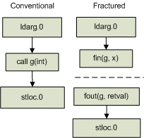
To fracture a data flow path, the instructions that define input parameters passed at a given call site are instead linked directly to the associated formal input parameter phi functions that are found in the context of the target procedure. Likewise, instructions that use output parameters previously defined by the call instruction are instead linked directly to the associated formal output parameter phi functions found in the context of the target procedure. This has the effect of breaking the original data flow path into two disconnected data flow paths at the call site location. The linking of actual parameters and call site parameters with formal parameters has been illustrated in previous literature. Horwitz, Reps, and Binkley used this concept during the construction of a system dependence graph (SDG)[7]. The concept of creating symbolic variables that are later used to link information together is not new[15]. Figure 2 provides an example of what a conventional and fractured data flow path might look like.
 |
Using the fracturing concept, the instruction tier's path-sensitive data flow information for a given procedure becomes disconnected. This helps to improve the overall accuracy of the data flow paths that are conveyed. Fracturing also has the added advantage of making it possible to use formal parameter phi functions to dynamically link a caller and a callee at runtime. This makes it possible to identify context-sensitive interprocedural data flow paths at the granularity of an instruction. This ability will be described in more detail when the reachability algorithm is described in §3.
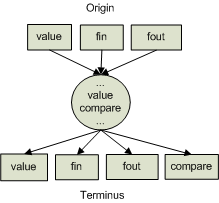
With an understanding of the benefits of fracturing, it is now possible to define the general form that data flow paths may take at the instruction tier. This general form is meant to describe the structure of data flow paths at the instruction tier in terms of the potential set of origins, transient, and terminal points with respect to the general instruction types. Based on the description given above, it is possible to categorize instructions into a few general types. Using these general instruction types, the general form of instruction data flow paths can be captured as illustrated by the diagram in figure 3.
- value: Defines or uses a data value
- compare: Compares a data value
- fin: Pseudo instruction representing a formal input parameter
- fout: Pseudo instruction representing a formal output parameter
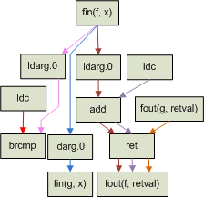
Based on this general description of instruction data flow paths, it is helpful to consider a concrete example. Consider the example source code described below which shows the implementation of the f function.
static public int f(int x)
{
   return (x > 0) ? g(x) : x + 1;
}
This function is intentionally very simple so as to limit the number of data flow paths that must be represented visually. Using the concepts described above, the instruction data flow paths that would be created as a result of analyzing this procedure are shown in figure 4. Note that the call site for the g function results in two disconnected data flow paths. The end result is that there are four unique data flow paths within this procedure, each denoted by a unique edge color.
 |