

| Current | v9 | v8 | v7 | v6 | v5 | v4 | v3 | v2 | v1 | All | About |
Determining the Stub's Base Address
The first step in most decoder stubs will require the use of a series of instructions, also referred to as geteip code, that obtain the location of the current instruction pointer. The reason this is necessary is because most decoders will have the encoded data placed immediately following the decoder stub in memory. In order to operate on the encoded data using an absolute address, it is necessary to determine where the data is at. If the decoder stub can determine the address that it's executing from, then it can determine the address of the encoded data immediately following it in memory in a position-independent fashion. As one might expect, the character limitations of this challenge make it quite a bit harder to get the value current instruction pointer.
There are a number of different techniques that can be used to get the value of the instruction pointer on x86[3]. However, the majority of these techniques rely on the use of the call instruction. The problem with the use of the call instruction is that it is generally composed of a high ASCII byte, such as 0xe8 or 0xff. Another technique that can be used to get the instruction pointer is the fnstenv FPU instruction. Unfortunately, this instruction is also composed of bytes in the high ASCII range, such as 0xd9. Yet another approach is to use structured exception handling to get the instruction pointer. This is accomplished by registering an exception handler and extracting the Eip value from the CONTEXT structure when an exception is generated. In fact, this approach has even been implemented in entirely alphanumeric form for Windows by SkyLined. Unfortunately, it can't be used in this case because it relies on uppercase characters.
With all of the known geteip techniques unusable, it seems like some alternative method for getting the base address of the decoder stub will be needed. In the world of alphanumeric encoders, such as SkyLined's Alpha2[4], it is common for the decoder stub to assume that a certain register contains the base address of the decoder stub. This assumption makes the decoder more complicated to use because it can't simply be dropped into any exploit and be expected to work. Instead, exploits may need to be modified in order to ensure that a register can be found that contains the location, or some location near, the decoder stub.
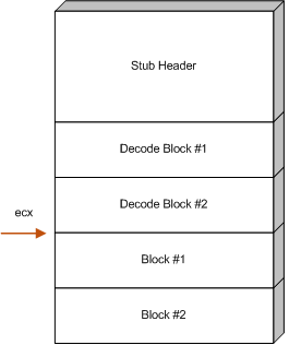
At the time of this writing, the author is not aware of a geteip technique that can be used that is both 7-bit safe and tolower safe. Like the alphanumeric payloads, the decoder described in this paper will be implemented using a register that is explicitly assumed to contain a reference to some address that is near the base address of the decoder stub. For this document, the register that is assumed to hold the address will be ecx, but it is equally possible to use other registers.
For this particular decoder, determining the base address is just
the first step involved in implementing the stub's header. Once the
base address has been determined, the decoder must adjust the
register that holds the base address to point to the location of the
encoded data. The reason this is necessary is because the next step
of the decoder, the transforms, depend on knowing the location of
the encoded data that they will be operating on. In order to
calculate this address, the decoder must add the size of the stub
header plus the size of the all of the decode transforms to the
register that holds the base address. The end result should be that
the register will hold the address of the first encoded block.
Figure ![[*]](images/html/crossref.png) illustrates where ecx should
point after this calculation is complete.
illustrates where ecx should
point after this calculation is complete.
The following disassembly shows one way that the stub header might be implemented. In this disassembly, ecx is assumed to point at the beginning of the stub header:
00000000  6A12              push byte +0x12
00000002  6B3C240B          imul edi,[esp],byte +0xb
00000006  60                pusha
00000007  030C24            add ecx,[esp]
0000000A  6A19              push byte +0x19
0000000C  030C24            add ecx,[esp]
0000000F  6A04              push byte +0x4
The purpose of the first two instructions is to calculate the number
of bytes consumed by all of the decode transforms (which are
described in section ). It accomplishes this by
multiplying the size of each transform, which is 0xb bytes,
by the total number of transforms, which in this example
0x12. The result of the multiplication, 0xc6, is
stored in edi. Since each transform is capable of decoding
four bytes of the raw payload, the maximum number of bytes that can
be encoded is 508 bytes. This shouldn't be seen as much of a
limiting factor, though, as other combinations of imul can
be used to account for larger payloads.
Once the size of the decode transforms has been calculated, pusha is executed in order to place the edi register at the top of the stack. With the value of edi at the top of the stack, the value can be added to the base address register ecx, thus accounting for the number of bytes used by the decode transforms. The astute reader might ask why the value of edi is indirectly added to ecx. Why not just add it directly? The answer, of course, is due to bad characters:
00000000 01F9 add ecx,edi
It's also not possible to simply push edi onto the stack, because the push edi instruction also contains bad characters:
00000000 57 push edi
Starting with the fifth instruction, the size of the stub header, plus any other offsets that may need to be accounted for, are added to the base address in order to shift the ecx register to point at the start of the encoded data. This is accomplished by simply pushing the the number of bytes to add onto the stack and then adding them to the ecx register indirectly by adding through [esp].
After these instructions are finished, ecx will point to the start of the encoded data. The final instruction in the stub header is a push byte 0x4. This instruction isn't actually used by the stub header, but it's there to set up some necessary state that will be used by the decode transforms. It's use will be described in the next section.